- All
- Product Name
- Product Keyword
- Product Model
- Product Summary
- Product Description
- Multi Field Search


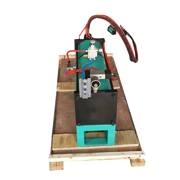 |


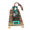
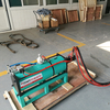
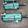
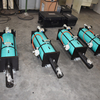


The pure pneumatic split-type ODMT gas-liquid booster cylinder is a combination of a gas-liquid booster MES and a working cylinder MAT OR MHZ. It can be driven by compressed air with a maximum of 6bar or 8bar and can generate 2KN-2000KN pressure. The hydraulic pressure is stored in the MES without the need for a hydraulic system. Simple structure, with absolutely strict gas-liquid isolation seal.
The control is the same as the general double-acting cylinder control, which is simple and reliable, low energy consumption, no impact and noise.
Each work process consists of the following three itineraries:
(1) Pure pneumatic fast travel;
(2) Force stroke of gas-liquid boost;
(3) Pneumatic back stroke.
Application:
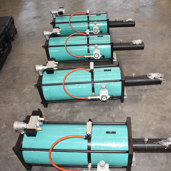
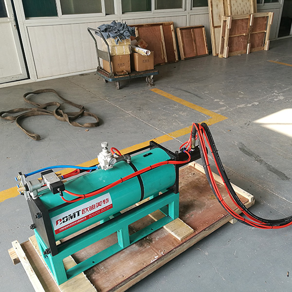
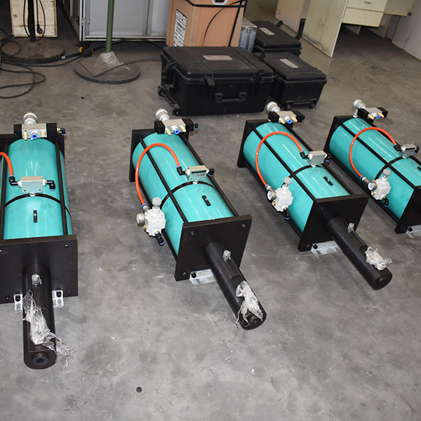
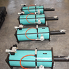
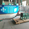
MT type gas-hydraulic booster cylinder can be used in applications with large force stroke and / or small installation space. A set of MT gas-liquid booster cylinders consists of a gas-liquid booster MES and one or more working cylinders. There are two types of working cylinders: MAT-type gas-hydraulic cylinder or MHY-type special hydraulic cylinder. The gas-liquid booster MES is separately installed from the working cylinder MAT or MHZ, and is connected by a high-pressure hose;
Maximum driving air pressure: 6bar or 8bar;
Impact pressure: 2KN-2000KN.
| Type | stroke tk | FKH t | FEH kgf | FRH kgf | V Cm³ | △V1 Cm³ | △V2 Cm | E | D | C | A | V | B | H | S | F | K | G | N | U | X |
MAT1 | 50 | 1.3 | 69 | 72 | 0.31 | 0.6 | 0.4 | 50 | 229 | 6-M6*11 | 40 | G1/8 | 30 | 10 | 16 | 36 | M12*1.5 | 12 | 14 | 6 | G1/2 |
MAT1 | 100 | 1.3 | 69 | 72 | 0.31 | 1.0 | 0.4 | 50 | 329 | 6-M6*11 | 40 | G1/8 | 30 | 10 | 16 | 36 | M12*1.5 | 12 | 14 | 6 | G1/2 |
MAT1 | 200 | 1.3 | 69 | 72 | 0.31 | 1.8 | 0.4 | 50 | 529 | 6-M6*11 | 40 | G1/8 | 30 | 10 | 16 | 36 | M12*1.5 | 12 | 14 | 6 | G1/2 |
MAT1 | 250 | 1.3 | 69 | 72 | 0.31 | 2.3 | 0.4 | 50 | 629 | 6-M6*11 | 40 | G1/8 | 30 | 10 | 16 | 36 | M12*1.5 | 12 | 14 | 6 | G1/2 |
MAT2 | 50 | 2.1 | 140 | 150 | 0.49 | 0.8 | 0.7 | 70 | 242 | 6-M8*12 | 54 | G1/4 | 40 | 10 | 20 | 41 | M16*1.5 | 15 | 17 | 8 | G1/2 |
MAT2 | 100 | 2.1 | 140 | 150 | 0.49 | 1.4 | 0.7 | 70 | 342 | 6-M8*12 | 54 | G1/4 | 40 | 10 | 20 | 41 | M16*1.5 | 15 | 17 | 8 | G1/2 |
MAT2 | 200 | 2.1 | 140 | 150 | 0.49 | 2.6 | 0.7 | 70 | 542 | 6-M8*12 | 54 | G1/4 | 40 | 10 | 20 | 41 | M16*1.5 | 15 | 17 | 8 | G1/2 |
MAT2 | 300 | 2.1 | 140 | 150 | 0.49 | 3.9 | 0.7 | 70 | 742 | 6-M8*12 | 54 | G1/4 | 40 | 10 | 20 | 41 | M16*1.5 | 15 | 17 | 8 | G1/2 |
MAT4 | 50 | 4.2 | 180 | 195 | 1.02 | 2.3 | 0.7 | 85 | 258 | 6-M8*15 | 64 | G3/8 | 50 | 10 | 30 | 48.5 | M22*2 | 20 | 24 | 10 | G1/2 |
MAT4 | 100 | 4.2 | 180 | 195 | 1.02 | 3.1 | 0.7 | 85 | 355 | 6-M8*15 | 64 | G3/8 | 50 | 10 | 30 | 48.5 | M22*2 | 20 | 24 | 10 | G1/2 |
MAT4 | 200 | 4.2 | 180 | 195 | 1.02 | 5.6 | 0.7 | 85 | 555 | 6-M8*15 | 64 | G3/8 | 50 | 10 | 30 | 48.5 | M22*2 | 20 | 24 | 10 | G1/2 |
MAT4 | 300 | 4.2 | 180 | 195 | 1.02 | 8.1 | 0.7 | 85 | 755 | 6-M8*15 | 64 | G3/8 | 50 | 10 | 30 | 48.5 | M22*2 | 20 | 24 | 10 | G1/2 |
MAT4 | 400 | 4.2 | 180 | 195 | 1.02 | 10.6 | 0.7 | 85 | 955 | 6-M8*15 | 64 | G3/8 | 50 | 10 | 30 | 48.5 | M22*2 | 20 | 24 | 10 | G1/2 |
MAT8 | 50 | 8.1 | 320 | 330 | 1.96 | 5.6 | 0.9 | 110 | 288 | 6-M10*16 | 88 | G1/2 | 70 | 10 | 45 | 60 | M30*2 | 25 | 36 | 12 | G3/4 |
MAT8 | 100 | 8.1 | 320 | 330 | 1.96 | 5.7 | 0.9 | 110 | 371 | 6-M10*16 | 88 | G1/2 | 70 | 10 | 45 | 60 | M30*2 | 25 | 36 | 12 | G3/4 |
MAT8 | 200 | 8.1 | 320 | 330 | 1.96 | 10.4 | 0.9 | 110 | 571 | 6-M10*16 | 88 | G1/2 | 70 | 10 | 45 | 60 | M30*2 | 25 | 36 | 12 | G3/4 |
MAT8 | 300 | 8.1 | 320 | 330 | 1.96 | 15.0 | 0.9 | 110 | 771 | 6-M10*16 | 88 | G1/2 | 70 | 10 | 45 | 60 | M30*2 | 25 | 36 | 12 | G3/4 |
MAT8 | 400 | 8.1 | 320 | 330 | 1.96 | 19.7 | 0.9 | 110 | 971 | 6-M10*16 | 88 | G1/2 | 70 | 10 | 45 | 60 | M30*2 | 25 | 36 | 12 | G3/4 |
MAT15 | 50 | 15.8 | 450 | 550 | 3.85 | 9.2 | 1.1 | 135 | 293 | 6-M16*25 | 100 | G1/2 | 75 | 15 | 50 | 61 | M30*2 | 25 | 41 | 16 | G1 |
MAT15 | 100 | 15.8 | 450 | 550 | 3.85 | 10.1 | 1.1 | 135 | 381 | 6-M16*25 | 100 | G1/2 | 75 | 15 | 50 | 61 | M30*2 | 25 | 41 | 16 | G1 |
MAT15 | 200 | 15.8 | 450 | 550 | 3.85 | 19.7 | 1.1 | 135 | 581 | 6-M16*25 | 100 | G1/2 | 75 | 15 | 50 | 61 | M30*2 | 25 | 41 | 16 | G1 |
MAT15 | 300 | 15.8 | 450 | 550 | 3.85 | 28.1 | 1.1 | 135 | 781 | 6-M16*25 | 100 | G1/2 | 75 | 15 | 50 | 61 | M30*2 | 25 | 41 | 16 | G1 |
MAT15 | 400 | 15.8 | 450 | 550 | 3.85 | 37.0 | 1.1 | 135 | 981 | 6-M16*25 | 100 | G1/2 | 75 | 15 | 50 | 61 | M30*2 | 25 | 41 | 16 | G1 |
| MAT30 | 50 | 32.0 | 660 | 930 | 7.85 | 19.3 | 2.2 | 170 | 362 | 6-M20*30 | 132 | G3/4 | 100 | 18 | 56 | 82 | M39*2 | 35 | 50 | 22 | G1 |
MAT30 | 100 | 32.0 | 660 | 930 | 7.85 | 22.5 | 2.2 | 170 | 425 | 6-M20*30 | 132 | G3/4 | 100 | 18 | 56 | 82 | M39*2 | 35 | 50 | 22 | G1 |
MAT30 | 200 | 32.0 | 660 | 930 | 7.85 | 40.4 | 2.2 | 170 | 625 | 6-M20*30 | 132 | G3/4 | 100 | 18 | 56 | 82 | M39*2 | 35 | 50 | 22 | G1 |
MAT30 | 300 | 32.0 | 660 | 930 | 7.85 | 58.4 | 2.2 | 170 | 825 | 6-M20*30 | 132 | G3/4 | 100 | 18 | 56 | 82 | M39*2 | 35 | 50 | 22 | G1 |
MAT30 | 400 | 32.0 | 660 | 930 | 7.85 | 76.4 | 2.2 | 170 | 1025 | 6-M20*30 | 132 | G3/4 | 100 | 18 | 56 | 82 | M39*2 | 35 | 50 | 22 | G1 |
| MAT50 | 50 | 49.8 | 720 | 1200 | 12.27 | 34.8 | 2.2 | 200 | 390 | 6-M20*30 | 150 | G3/4 | 115 | 25 | 63 | 92 | M42*2 | 40 | 55 | 30 | G1 |
| MAT50 | 100 | 49.8 | 720 | 1200 | 12.27 | 34.8 | 2.2 | 200 | 440 | 6-M20*30 | 150 | G3/4 | 115 | 25 | 63 | 92 | M42*2 | 40 | 55 | 30 | G1 |
| MAT50 | 200 | 49.8 | 720 | 1200 | 12.27 | 62.7 | 2.2 | 200 | 640 | 6-M20*30 | 150 | G3/4 | 115 | 25 | 63 | 92 | M42*2 | 40 | 55 | 30 | G1 |
| MAT50 | 300 | 49.8 | 720 | 1200 | 12.27 | 90.5 | 2.2 | 200 | 840 | 6-M20*30 | 150 | G3/4 | 115 | 25 | 63 | 92 | M42*2 | 40 | 55 | 30 | G1 |
| MAT100 | 100 | 103.0 | 1260 | 2200 | 25.45 | 71.5 | 3.1 | 310 | 534 | 12-M24*40 | 200 | G1 | 150 | 25 | 100 | 120 | M64*2 | 60 | 85 | 30 | G1 |
| MAT100 | 200 | 103.0 | 1260 | 2200 | 25.45 | 128.7 | 3.1 | 310 | 734 | 12-M24*40 | 200 | G1 | 150 | 25 | 100 | 120 | M64*2 | 60 | 85 | 30 | G1 |
| MAT100 | 300 | 103.0 | 1260 | 2200 | 25.45 | 185.9 | 3.1 | 310 | 934 | 12-M24*40 | 200 | G1 | 150 | 25 | 100 | 120 | M64*2 | 60 | 85 | 30 | G1 |
| MAT200 | 200 | 199.4* | 1760 | 2860 | 38.01 | 178.8 | 3.6 | 420 | 829 | 18-M30*55 | 320 | G3/4 | 240 | 35 | 150 | 150 | M80*2 | 80 | 4*ø16 | 30 | G1 |
The pure pneumatic split-type ODMT gas-liquid booster cylinder is a combination of a gas-liquid booster MES and a working cylinder MAT OR MHZ. It can be driven by compressed air with a maximum of 6bar or 8bar and can generate 2KN-2000KN pressure. The hydraulic pressure is stored in the MES without the need for a hydraulic system. Simple structure, with absolutely strict gas-liquid isolation seal.
The control is the same as the general double-acting cylinder control, which is simple and reliable, low energy consumption, no impact and noise.
Each work process consists of the following three itineraries:
(1) Pure pneumatic fast travel;
(2) Force stroke of gas-liquid boost;
(3) Pneumatic back stroke.
Application:
MT type gas-hydraulic booster cylinder can be used in applications with large force stroke and / or small installation space. A set of MT gas-liquid booster cylinders consists of a gas-liquid booster MES and one or more working cylinders. There are two types of working cylinders: MAT-type gas-hydraulic cylinder or MHY-type special hydraulic cylinder. The gas-liquid booster MES is separately installed from the working cylinder MAT or MHZ, and is connected by a high-pressure hose;
Maximum driving air pressure: 6bar or 8bar;
Impact pressure: 2KN-2000KN.
| Type | stroke tk | FKH t | FEH kgf | FRH kgf | V Cm³ | △V1 Cm³ | △V2 Cm | E | D | C | A | V | B | H | S | F | K | G | N | U | X |
MAT1 | 50 | 1.3 | 69 | 72 | 0.31 | 0.6 | 0.4 | 50 | 229 | 6-M6*11 | 40 | G1/8 | 30 | 10 | 16 | 36 | M12*1.5 | 12 | 14 | 6 | G1/2 |
MAT1 | 100 | 1.3 | 69 | 72 | 0.31 | 1.0 | 0.4 | 50 | 329 | 6-M6*11 | 40 | G1/8 | 30 | 10 | 16 | 36 | M12*1.5 | 12 | 14 | 6 | G1/2 |
MAT1 | 200 | 1.3 | 69 | 72 | 0.31 | 1.8 | 0.4 | 50 | 529 | 6-M6*11 | 40 | G1/8 | 30 | 10 | 16 | 36 | M12*1.5 | 12 | 14 | 6 | G1/2 |
MAT1 | 250 | 1.3 | 69 | 72 | 0.31 | 2.3 | 0.4 | 50 | 629 | 6-M6*11 | 40 | G1/8 | 30 | 10 | 16 | 36 | M12*1.5 | 12 | 14 | 6 | G1/2 |
MAT2 | 50 | 2.1 | 140 | 150 | 0.49 | 0.8 | 0.7 | 70 | 242 | 6-M8*12 | 54 | G1/4 | 40 | 10 | 20 | 41 | M16*1.5 | 15 | 17 | 8 | G1/2 |
MAT2 | 100 | 2.1 | 140 | 150 | 0.49 | 1.4 | 0.7 | 70 | 342 | 6-M8*12 | 54 | G1/4 | 40 | 10 | 20 | 41 | M16*1.5 | 15 | 17 | 8 | G1/2 |
MAT2 | 200 | 2.1 | 140 | 150 | 0.49 | 2.6 | 0.7 | 70 | 542 | 6-M8*12 | 54 | G1/4 | 40 | 10 | 20 | 41 | M16*1.5 | 15 | 17 | 8 | G1/2 |
MAT2 | 300 | 2.1 | 140 | 150 | 0.49 | 3.9 | 0.7 | 70 | 742 | 6-M8*12 | 54 | G1/4 | 40 | 10 | 20 | 41 | M16*1.5 | 15 | 17 | 8 | G1/2 |
MAT4 | 50 | 4.2 | 180 | 195 | 1.02 | 2.3 | 0.7 | 85 | 258 | 6-M8*15 | 64 | G3/8 | 50 | 10 | 30 | 48.5 | M22*2 | 20 | 24 | 10 | G1/2 |
MAT4 | 100 | 4.2 | 180 | 195 | 1.02 | 3.1 | 0.7 | 85 | 355 | 6-M8*15 | 64 | G3/8 | 50 | 10 | 30 | 48.5 | M22*2 | 20 | 24 | 10 | G1/2 |
MAT4 | 200 | 4.2 | 180 | 195 | 1.02 | 5.6 | 0.7 | 85 | 555 | 6-M8*15 | 64 | G3/8 | 50 | 10 | 30 | 48.5 | M22*2 | 20 | 24 | 10 | G1/2 |
MAT4 | 300 | 4.2 | 180 | 195 | 1.02 | 8.1 | 0.7 | 85 | 755 | 6-M8*15 | 64 | G3/8 | 50 | 10 | 30 | 48.5 | M22*2 | 20 | 24 | 10 | G1/2 |
MAT4 | 400 | 4.2 | 180 | 195 | 1.02 | 10.6 | 0.7 | 85 | 955 | 6-M8*15 | 64 | G3/8 | 50 | 10 | 30 | 48.5 | M22*2 | 20 | 24 | 10 | G1/2 |
MAT8 | 50 | 8.1 | 320 | 330 | 1.96 | 5.6 | 0.9 | 110 | 288 | 6-M10*16 | 88 | G1/2 | 70 | 10 | 45 | 60 | M30*2 | 25 | 36 | 12 | G3/4 |
MAT8 | 100 | 8.1 | 320 | 330 | 1.96 | 5.7 | 0.9 | 110 | 371 | 6-M10*16 | 88 | G1/2 | 70 | 10 | 45 | 60 | M30*2 | 25 | 36 | 12 | G3/4 |
MAT8 | 200 | 8.1 | 320 | 330 | 1.96 | 10.4 | 0.9 | 110 | 571 | 6-M10*16 | 88 | G1/2 | 70 | 10 | 45 | 60 | M30*2 | 25 | 36 | 12 | G3/4 |
MAT8 | 300 | 8.1 | 320 | 330 | 1.96 | 15.0 | 0.9 | 110 | 771 | 6-M10*16 | 88 | G1/2 | 70 | 10 | 45 | 60 | M30*2 | 25 | 36 | 12 | G3/4 |
MAT8 | 400 | 8.1 | 320 | 330 | 1.96 | 19.7 | 0.9 | 110 | 971 | 6-M10*16 | 88 | G1/2 | 70 | 10 | 45 | 60 | M30*2 | 25 | 36 | 12 | G3/4 |
MAT15 | 50 | 15.8 | 450 | 550 | 3.85 | 9.2 | 1.1 | 135 | 293 | 6-M16*25 | 100 | G1/2 | 75 | 15 | 50 | 61 | M30*2 | 25 | 41 | 16 | G1 |
MAT15 | 100 | 15.8 | 450 | 550 | 3.85 | 10.1 | 1.1 | 135 | 381 | 6-M16*25 | 100 | G1/2 | 75 | 15 | 50 | 61 | M30*2 | 25 | 41 | 16 | G1 |
MAT15 | 200 | 15.8 | 450 | 550 | 3.85 | 19.7 | 1.1 | 135 | 581 | 6-M16*25 | 100 | G1/2 | 75 | 15 | 50 | 61 | M30*2 | 25 | 41 | 16 | G1 |
MAT15 | 300 | 15.8 | 450 | 550 | 3.85 | 28.1 | 1.1 | 135 | 781 | 6-M16*25 | 100 | G1/2 | 75 | 15 | 50 | 61 | M30*2 | 25 | 41 | 16 | G1 |
MAT15 | 400 | 15.8 | 450 | 550 | 3.85 | 37.0 | 1.1 | 135 | 981 | 6-M16*25 | 100 | G1/2 | 75 | 15 | 50 | 61 | M30*2 | 25 | 41 | 16 | G1 |
| MAT30 | 50 | 32.0 | 660 | 930 | 7.85 | 19.3 | 2.2 | 170 | 362 | 6-M20*30 | 132 | G3/4 | 100 | 18 | 56 | 82 | M39*2 | 35 | 50 | 22 | G1 |
MAT30 | 100 | 32.0 | 660 | 930 | 7.85 | 22.5 | 2.2 | 170 | 425 | 6-M20*30 | 132 | G3/4 | 100 | 18 | 56 | 82 | M39*2 | 35 | 50 | 22 | G1 |
MAT30 | 200 | 32.0 | 660 | 930 | 7.85 | 40.4 | 2.2 | 170 | 625 | 6-M20*30 | 132 | G3/4 | 100 | 18 | 56 | 82 | M39*2 | 35 | 50 | 22 | G1 |
MAT30 | 300 | 32.0 | 660 | 930 | 7.85 | 58.4 | 2.2 | 170 | 825 | 6-M20*30 | 132 | G3/4 | 100 | 18 | 56 | 82 | M39*2 | 35 | 50 | 22 | G1 |
MAT30 | 400 | 32.0 | 660 | 930 | 7.85 | 76.4 | 2.2 | 170 | 1025 | 6-M20*30 | 132 | G3/4 | 100 | 18 | 56 | 82 | M39*2 | 35 | 50 | 22 | G1 |
| MAT50 | 50 | 49.8 | 720 | 1200 | 12.27 | 34.8 | 2.2 | 200 | 390 | 6-M20*30 | 150 | G3/4 | 115 | 25 | 63 | 92 | M42*2 | 40 | 55 | 30 | G1 |
| MAT50 | 100 | 49.8 | 720 | 1200 | 12.27 | 34.8 | 2.2 | 200 | 440 | 6-M20*30 | 150 | G3/4 | 115 | 25 | 63 | 92 | M42*2 | 40 | 55 | 30 | G1 |
| MAT50 | 200 | 49.8 | 720 | 1200 | 12.27 | 62.7 | 2.2 | 200 | 640 | 6-M20*30 | 150 | G3/4 | 115 | 25 | 63 | 92 | M42*2 | 40 | 55 | 30 | G1 |
| MAT50 | 300 | 49.8 | 720 | 1200 | 12.27 | 90.5 | 2.2 | 200 | 840 | 6-M20*30 | 150 | G3/4 | 115 | 25 | 63 | 92 | M42*2 | 40 | 55 | 30 | G1 |
| MAT100 | 100 | 103.0 | 1260 | 2200 | 25.45 | 71.5 | 3.1 | 310 | 534 | 12-M24*40 | 200 | G1 | 150 | 25 | 100 | 120 | M64*2 | 60 | 85 | 30 | G1 |
| MAT100 | 200 | 103.0 | 1260 | 2200 | 25.45 | 128.7 | 3.1 | 310 | 734 | 12-M24*40 | 200 | G1 | 150 | 25 | 100 | 120 | M64*2 | 60 | 85 | 30 | G1 |
| MAT100 | 300 | 103.0 | 1260 | 2200 | 25.45 | 185.9 | 3.1 | 310 | 934 | 12-M24*40 | 200 | G1 | 150 | 25 | 100 | 120 | M64*2 | 60 | 85 | 30 | G1 |
| MAT200 | 200 | 199.4* | 1760 | 2860 | 38.01 | 178.8 | 3.6 | 420 | 829 | 18-M30*55 | 320 | G3/4 | 240 | 35 | 150 | 150 | M80*2 | 80 | 4*ø16 | 30 | G1 |


We warmly welcome the dealers local and abroad to negotiate business and work hand in hand with us for progress.

