- All
- Product Name
- Product Keyword
- Product Model
- Product Summary
- Product Description
- Multi Field Search


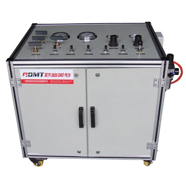 |


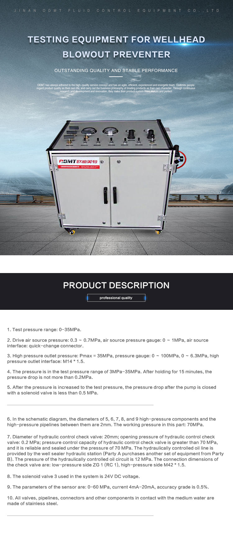
1. Test pressure range: 0-35MPa.
2. Drive air source pressure: 0.3 ~ 0.7MPa, air source pressure gauge: 0 ~ 1MPa, air source interface: quick-change connector.
3. High pressure outlet pressure: Pmax = 35MPa, pressure gauge: 0 ~ 100MPa, 0 ~ 6.3MPa, high pressure outlet interface: M14 * 1.5.
4. The pressure is in the test pressure range of 3MPa-35MPa. After holding for 15 minutes, the pressure drop is not more than 0.2MPa.
5. After the pressure is increased to the test pressure, the pressure drop after the pump is closed with a solenoid valve is less than 0.5 MPa.
6. In the schematic diagram, the diameters of 5, 6, 7, 8, and 9 high-pressure components and the high-pressure pipelines between them are 2mm. The working pressure in this part: 70MPa.
7. Diameter of hydraulic control check valve: 20mm; opening pressure of hydraulic control check valve: 0.2 MPa; pressure control capacity of hydraulic control check valve is greater than 70 MPa, and it is reliable and sealed under the pressure of 70 MPa. The hydraulically controlled oil line is provided by the well sealer hydraulic station (Party A purchases another set of equipment from Party B). The pressure of the hydraulically controlled oil circuit is 12 MPa. The connection dimensions of the check valve are: low-pressure side ZG 1 (RC 1), high-pressure side M42 * 1.5.
8. The solenoid valve 3 used in the system is 24V DC voltage.
9. The parameters of the sensor are: 0-60 MPa, current 4mA-20mA, accuracy grade is 0.5%.
10. All valves, pipelines, connectors and other components in contact with the medium water are made of stainless steel.
Implement the function:
In addition to the technical parameters required for the high-pressure hydraulic test stand of the well sealer, it shall also have the following functions:
1. After connecting the required air and water sources, the pneumatic pump will automatically press down (in the state where the manual directional valve is opened or the two-position three-way valve is controlled to be in the corresponding position), and when the set pressure is reached, the air pump will automatically stop pressing .
2. When holding pressure is required, the two-position two-way valve controls the pneumatic high-pressure needle valve to be cut off, and then the pump is stopped to meet the accuracy requirements of holding pressure.
3. When releasing pressure, open the manual unloading valve or electronically controlled two-position two-way valve to control the pneumatic high-pressure unloading valve to realize the function of manual and automatic pressure relief to 0MPa.
4. The safety protection of the pump depends on the pressure regulating valve, which should be stable and reliable.
5. The water tank should be equipped with automatic water supply function.
6. When the low pressure water source has a pressure of 0.2MPa, the hydraulic control check valve opens to achieve the water injection function; during the pressure maintaining process, the hydraulic control check valve has no leakage; after the pressure is released, the hydraulic control check valve has a set pressure in the oil circuit. After that, the hydraulic control check valve opens, and then the drainage valve is opened to realize the drainage function.
7. The manual directional valve, air-controlled shut-off valve and electromagnetic directional valve are reliable and stable in controlling the corresponding pressure. The pressure drop of the entire system must meet the system parameter requirements.


We warmly welcome the dealers local and abroad to negotiate business and work hand in hand with us for progress.

