- All
- Product Name
- Product Keyword
- Product Model
- Product Summary
- Product Description
- Multi Field Search
 |
YFJ-D600
ODMT
20105551
I.Introduction
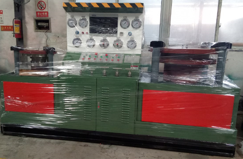
YFJ-D600 type hydraulic butterfly valve test bench is based on our years of production of valve testing equipment technology in strict accordance with the ISO9001 quality management system for management and production. Products meet GB/T13927-2008 "Universal valve pressure test", GB/T26480-2011 "valve test and inspection" and AP1598 American standard and other relevant standards.
Our hydraulic butterfly valve test bench set hydraulic, mechanical, electrical and media storage cycle combination in one, has the advantages of reasonable structure, perfect function, stable performance, high degree of automation, widely used in nominal diameter DN50-600mm straight flange or clamp butterfly valve sealing and strength and other performance tests, Is the valve manufacturing, petroleum and petrochemical, natural gas, water supply and drainage engineering, power plant, valve maintenance station and other industry units the most ideal valve test and testing equipment.
II.Butterfly Valve Test bench Structure and Working Principle
1. hydraulic butterfly valve test bench consists of hydraulic system, electrical control system, high and low pressure water pump pressure supply device system, oil pressure, water pressure instrument system, control valve system, clamping workbench system and hydraulic medium storage circulating water tank. The test process and results conform to relevant regulations and requirements.
2.The test bench uses the clamping claw to directly clamp the opposite flange surface of the butterfly valve, and the clamping mechanism is directly driven by the clamping cylinder of the clamping claw to work. The clamping claw can move forward and backward in the axial direction without being limited by the thickness. The radial movement is composed of oil cylinder and lever to realize the radial synchronous movement of each clamping claw, and the radial clamping claw can move forward and backward It is not limited by the flange diameter of butterfly valve. The test bench is divided into single type and combined type according to the valve specifications, which ensures butterfly valves of different sizes and diameters, wafer check valves, strength performance tests and air tightness performance tests.
3.The high-pressure water pump is powered by a 4-7bar air pressure system, and automatically reverses through an electric control reversing valve to enable the high-pressure water pump to automatically reciprocate. The water suction check valve and water outlet check valve are interchanged to continuously supply pressure to the valve under test to meet the pressure requirements of the valve under test.
4.It is applicable to flange butterfly valve and wafer butterfly valve 1.1 times nominal pressure high pressure water seal test, 1.5 times nominal pressure high pressure water shell test, 4-7bar low pressure air seal test.
5.Working process: according to the nominal diameter and pressure of the butterfly valve, adjust the pressure of the oil cylinder (refer to the pressure comparison table) - compress the workpiece - open the low water pump for rapid water injection - open the high pressure water pump - hold the pressure gauge - release and reset.
6. The pressure cylinder and medium pressure interlock function is set: when there is pressure in the test valve chamber, the pressure cylinder cannot be released. It plays a protective role in case of operation error.
7.The hydraulic system is equipped with a cooling fan.
8.All upper and lower sealing heads shall be made by the buyer.
9.The Demander shall provide 46 # anti-wear hydraulic oil, cable and 4-7bar air source.
We warmly welcome the dealers local and abroad to negotiate business and work hand in hand with us for progress.


